Set the speed
Turn the pot or tap the touch screen. The rotator holds the surface speed you chose.
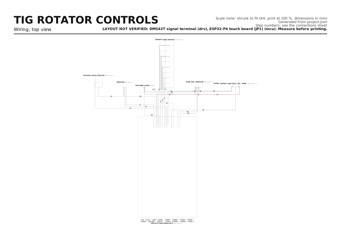
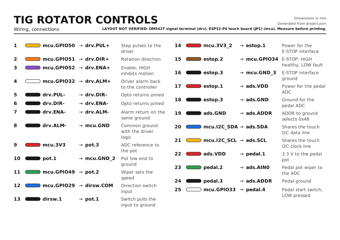
The control box wiring for an ESP32-P4 welding rotator: speed pot, direction switch, foot pedal and a supervised E-STOP input, generated from one project file.
The low-voltage controller subsystem of the DIY TIG welding positioner: the GUITION JC4880P443C ESP32-P4 touch board, its speed pot, direction switch, foot pedal (switch plus ADS1115 pot), conditioned E-STOP input and the DM542T signal terminal. Motor power, the stepper, gearbox and the grounded metal enclosure are outside this package.
Turn the pot or tap the touch screen. The rotator holds the surface speed you chose.
Press the pedal to start and let go to stop, so both hands stay on the torch and filler.
The E-STOP input and the driver alarm make the firmware stop pulses and inhibit ENA, and need a reset before it runs again. This path goes through the controller and does not disconnect motor power.
The wiring guide and the firmware pin header come from the same file, so GPIO numbers cannot drift apart.
The DM542T alarm output is read back, so a driver that reports a fault (over-current, over-voltage) stops the job. It cannot see a stall without an encoder.
An ADS1115 on the touch I2C bus reads the pedal pot, leaving the board ADC for the panel pot.
Everything lives in one grounded metal enclosure with the driver and PSU, which TIG HF start requires.
Drawn from the same files the case is printed from.
7 parts. Total: about 20 USD, estimated from typical prices, not sourced.
Hand-wired. The guide is drawn to scale from the real parts, one connection per step, with a close-up of every pad.
Open files, no account. Print it, order it, flash it.
No. TIG HF start needs the controller, driver and PSU in one grounded metal enclosure. This package leaves the enclosure out on purpose.
No. It is a supervised input on GPIO34 that the firmware acts on through ENA. It is not independent of the controller and does not cut motor power. Verify pressed, released, broken wire and power loss against docs/estop_timing.md before use.
The firmware and pin map have run on the owner's machine (v2.3.1). This generated guide has not been followed by anyone yet; check each step against HARDWARE_SETUP.md.
Only if your driver's input specification allows 3.3 V drive. The checker flags it as marginal; use a level interface if the manual asks for 5 V signals.
One download with the guide, the files and the firmware.